Metric Calculations
The following calculation functions are available to create Metrics in QRiS from Data Capture Event (DCE) layers. Each calculation function has a set of parameters that can be used to customize the calculation.
Count
This calculation counts the number of features from any number of DCE layers (with the addition of an optional count field) that fall within the sample frame. DCE layers may have an optional attribute filter applied. For lines and polygons, the count is prorated by length and area respectively. This function can also apply a valley centerline normalization.
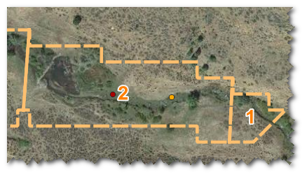
Count calculation example. Sample Frames are shown in orange dashed outline and labeled 1 and 2. Geomorphic Unit Points are mapped as red ("Mound") and orange ("Saddle") points. Depending on how the metric calculation is configured, the count could include all the Geomorphic Unit features that fall within the Sample Frame, or only those that are within the Sample Frame and have a specific attribute value (e.g. type = "Mound").
calculation_name: count
metric params:
layers: A list of DCE layers to count features from.
Each layer can have the following parameters:
count_field: An optional field which represents feature count values. These values will be used instead of counting up the number of individual features.attribute_filter: An optional attribute filter to apply to the DCE layers.
To apply a valley centerline normalization, the following parameter can be used:
normalization: centerline
Length
The length calculation sums the length of all features from any number of DCE layers that fall within the sample frame. DCE layers may have an optional attribute filter applied. This function can also apply a valley centerline normalization.
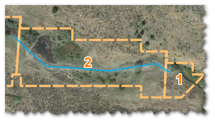
Length calculation example. Sample Frames are shown in orange dashed outline and labeled 1 and 2. The Active Channel Centerline feature is shown in blue. The metric calculation will sum the length of all Active Channel Centerline features that fall within the area of each Sample Frame.
calculation_name: length
metric params:
layers: A list of DCE layers to sum lengths from.
Each layer can have the following parameters:
attribute_filter: An optional attribute filter to apply to the DCE layers.
To apply a valley centerline normalization, the following parameter can be used:
- `normalization: centerline'
Area
The area calculation sums the area of all features from any number of DCE layers that fall within the sample frame. DCE layers may have an optional attribute filter applied. This function can also apply a valley centerline normalization.
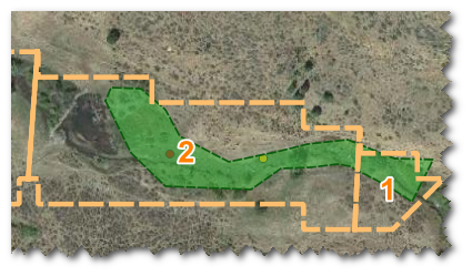
Area calculation example. Sample Frames are shown in orange dashed outline and labeled 1 and 2. The area of the vegetation extent polygon feature is shown in green. The metric calculation will sum the area of all vegetation extent features that fall within the area of each Sample Frame.
calculation_name: area
metric params:
layers: A list of DCE layers to sum areas from.
Each layer can have the following parameters:
attribute_filter: An optional attribute filter to apply to the DCE layers.
To apply a valley centerline normalization, the following parameter can be used:
normalization: centerline
Sinuosity
The sinuosity calculation first clips a line feature to the sample frameElement, then divides the length of the clipped line feature by the straight-line distance between the start and end points of the line.
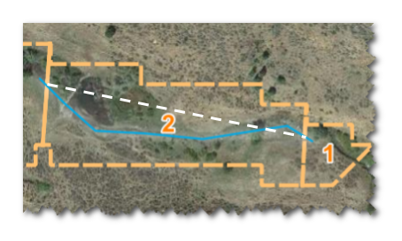
*Sinuosity calculation example. Sample Frames are shown in orange dashed outline and labeled 1 and 2. The Active Channel Centerline feature is shown in blue. The straight line distance of the Active Channel Centerline within Sample Frame #2 is shown in the white dashed line. The sinuosity for Sample Frame #2 is calculated as the length of the Active Channel Centerline within the Sample Frame divided by the straight line distance.
calculation_name: sinuosity
metric params:
layers: A list of one DCE layer to calculate sinuosity from.
Gradient
The gradient calculation calculates the average gradient of a line feature. The gradient is calculated as the difference in elevation between the start and end points of the line divided by the length of the line. Elevation is determined by the DEM layer.
Gradient calculation example. Sample Frames are shown in orange dashed outline and labeled 1 and 2. The Active Channel Centerline feature is shown in blue. Elevation from the DEM (not displayed) is sampled at the start and end points of the Active Channel Centerline clipped to the Sample Frame. The gradient is calculated as the difference in elevation between the start and end points of the Active Channel Centerline within the Sample Frame divided by the length of the Active Channel Centerline within the Sample Frame.
calculation_name: gradient
metric params:
layers: A list of one DCE layer to calculate gradient from.surfaces: a list of onedemsurface to use for elevation data.
Area Proportion
The area proportion calculation calculates the proportion of the area of a polygon feature that falls within the sample frame or other specified layers.
calculation_name: area_proportion
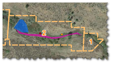
Area Proportion calculation example. Sample Frames are shown in orange dashed outline and labeled 1 and 2. Geomorphic Unit Polygons for "Free Flowing" (magenta) and "Ponded" (blue) are shown. Several types of area proportion metrics could be calculated from these layers, such as the proportion of the area of "Free Flowing" Geomorphic Units within the total area of the Sample Frame or the proportion of area of "Free Flowing" to total area of the Geomorphic Units (i.e. "Free Flowing" / ("Free Flowing" + "Ponded")).
metric params:
layers: A list of DCE layers to calculate area proportions from.
Each layer can have the following parameters:
usage: An optional field which represents that the layer should be used as anumeratorordenominatorin the calculation.- If not provided for a layer, then the layer will be used as a
numerator. - If no
denominatoris provided, the sample frame area will be used as the denominator.
- If not provided for a layer, then the layer will be used as a
attribute_filter: An optional attribute filter to apply to the DCE layers.
Additional calculations will be added as needed.