Analyses
QRiS analyses help track river health over time. Before you can perform an analysis you need to have a project with the following:
- One or more data capture events that represent the points in time for which you want to measure riverscape health. These events represent past, present or future representations of your riverscape captured as assessments, designs, plans or monitoring events. Each event must have geospatial features digitized (for automatic metric calculations). Manual entry of metric values do not require features to be digitized.
- A sample frame, valley bottom, or AOI that subdivides your riverscape into the spatial units for which you want to report river health. Typically these are polygons that span valley wall to valley wall and represent the river reaches or sub-reaches. However, they can also represent other spatial units such as reach typing or geomorphic setting depending on your desired analysis.
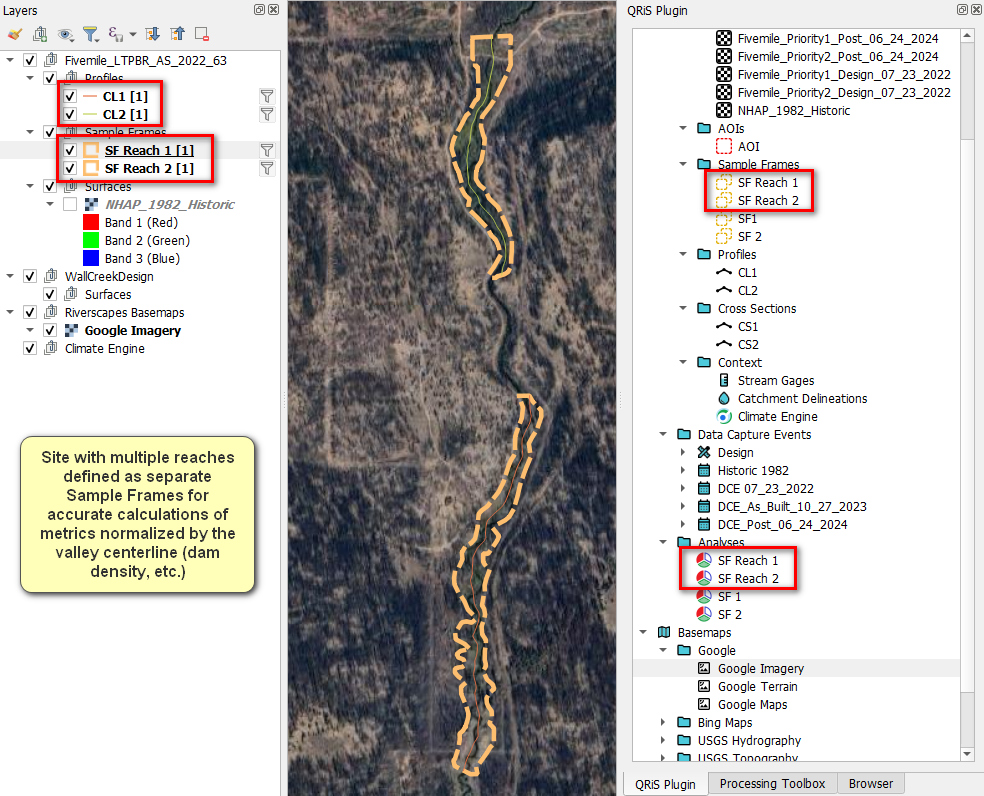
If multiple, spatially separate, reaches exist in a project multiple analyses will need to be done. Each reach will have its own distinct centerline which is used for calculating metrics, so it is necessary that they be analyzed separately.
Creating an analysis
Right click on the Analyses folder in the QRiS project tree and select Create New Analysis. This will open the analysis properties form. Provide a name and description for the analysis. Select the Analysis Masks (sample frame), valley bottom, centerline, and DEM (optional) you want to use for the analysis. You cannot change this once the analysis has been created. If you make a mistake you will need to delete the analysis and start again.
It is possible to choose an AOI or Riverscapes polygon as your Analysis Mask (sample frame).
Next, pick from the list of available metrics for production grade and experimental protocols that you want to include in your analysis. These can be found under the Metrics and Indicators tab. You can always add or remove metrics later after the analysis is created.
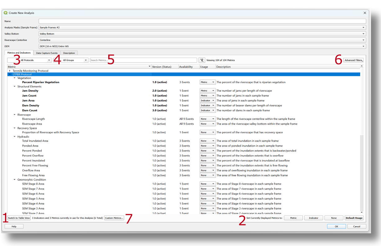
Each metric will show its version number, availability, usage, and description. The availability shows how many DCEs have layers populated with data to calculate a numeric value for the metric. The usage can be populated as one of three states:
- None - the metric will not be included in the analysis
- Metric - the metric will be included and treated as detailed metric when users want to dig into the full details of the analysis.
- Indicator - the metric will be included and treated as an indicator. Indicators are considered summary values, or shortlisted metrics for overall reporting.
Once a metric is selected as a metric or indicator, the version column will be bolded to show it as being active in the analysis.
Details
Additional Information
There are also multiple filters and menubars the user can utilize to refine their search and selection of metrics. In the bottom left hand corner (1), users can change the main window from tree view to table view or vice versa. The tree view shows metrics organized by dropdowns for each listed protocol, while the table view shows all metrics in a single, tabular list. In the bottom right hand corner (2), users can set all visible metrics as None, Metric, Indicator, or Default Usage (defined in protocol xml) using the buttons provided.
Users can also filter the metrics by the specific protocol (3), associated group (4), or search for specific metric names/keywords in the search bar (5). Advanced filters (6) can be used to further refine metric selection by ones currently in use, whether they are automated or manual, or display metrics included in experimental protocols or have been deprecated by protocol authors.
Finally, users can also set custom metrics to be included in the analysis. This can be done by clicking on the Custom Metrics tab (7) where users can define the parameters of the custom metric to be included in the analysis. Note: Custom metric values have to be manually populated by the user.
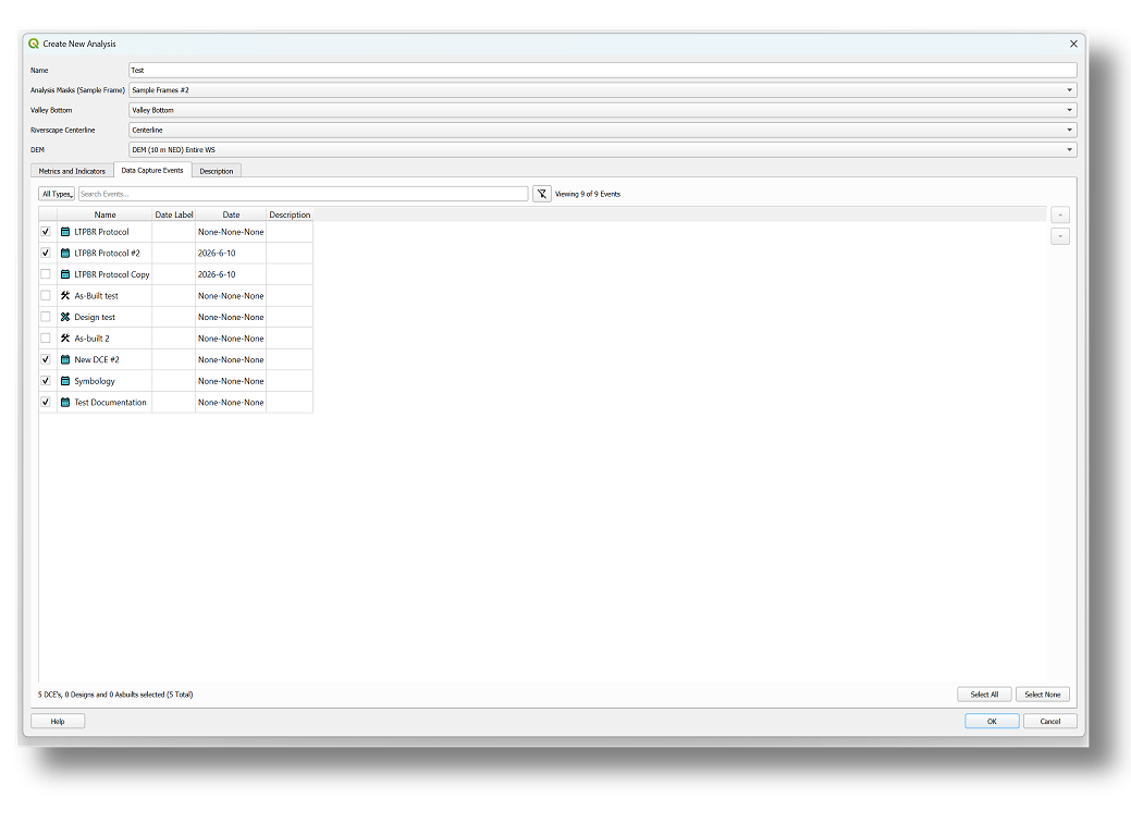
Once you have selected the metrics and indicators to be included in your analysis, click on the Data Capture Events tab to select the DCEs, designs, and/or as-builts you want to include in your analysis. This can be done by checking the box next to each DCE you want to include. You can also select all or none of the DCEs using the buttons in the bottom right hand corner.
Finally, you can populate the Description tab with any additional information you want to include about the analysis. This is optional and can be left blank.
Click OK to create the analysis.
Calculating Metric Values
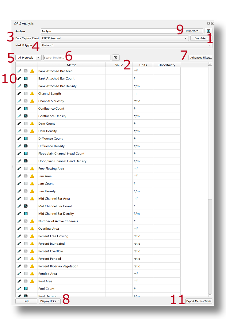
Once you are done finalizing the the analysis properties form, the metric table window will appear showing the list of metric included in your analysis. This is where you will view calculated values for associated data capture events and sample frames. To calculate numeric values for these metrics, simply click on the Calculate tab (1) in the upper right hand corner.
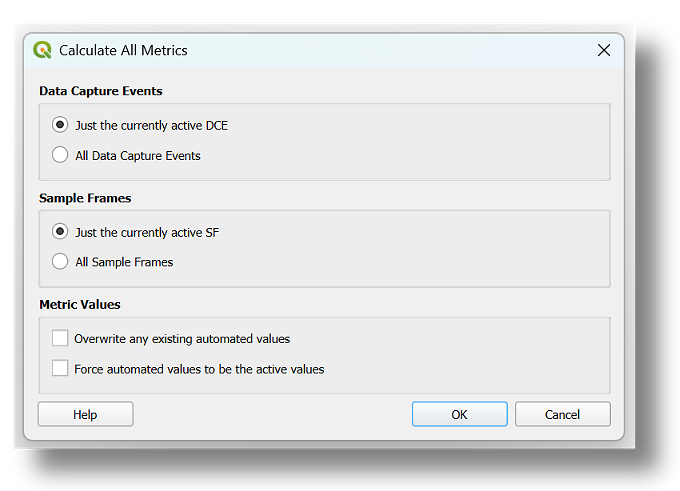
A separate window will appear allowing the user to calculate metric values for the currently selected DCE and Sample Frame, or for all Data Capture Events and Sample Frames denoted in the analysis properties form. Optionally, you can also overwrite existing values by clicking on the Overwrite any existing automated values box (ideal for changes to spatial data), or force values to be active by clicking on the Force automated values to be the active values. Once the user is satisfied with their selected options, click Ok to start metric calculation. A progress bar will display at the bottom of the QGIS UI showing progress towards completion.
Selecting all in both cases is an easy way to calculate all metrics across all sample frames and DCEs. Calculating just the currently active is a good way to run calculations to test output values and troubleshoot possible failed calculations.
Metric Table
Once an analysis is complete, metric values will populate under the Value column (2). Values will populate for the currently selected DCE & sample frame. Users can view metrics for different DCEs & sample frame polygons by using the Data Capture Event (3) and Mask Polygon (4) tabs respectively to change the selection. Furthermore, users can view metrics by protocol using the dropdown menu (5), search for specific metric(s) in the search bar (6), filter metrics under the Advanced Filters tab (7), or change the display units using the Display Units tab (8). To review the properties of the analysis form, select the Properties tab in the upper right hand corner (9).
Availability Matrix
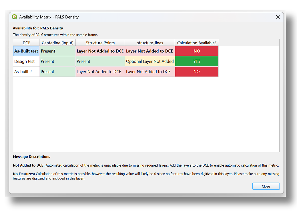
A yellow warning sign may appear next to a metric once the analysis is complete. This is to denote that the metric was not calculated. This can be due to layers containing no features, or the metric missing one or more required layers to calculate properly. Click on the warning sign to see the availability matrix window for diagnosis.
Metric Properties
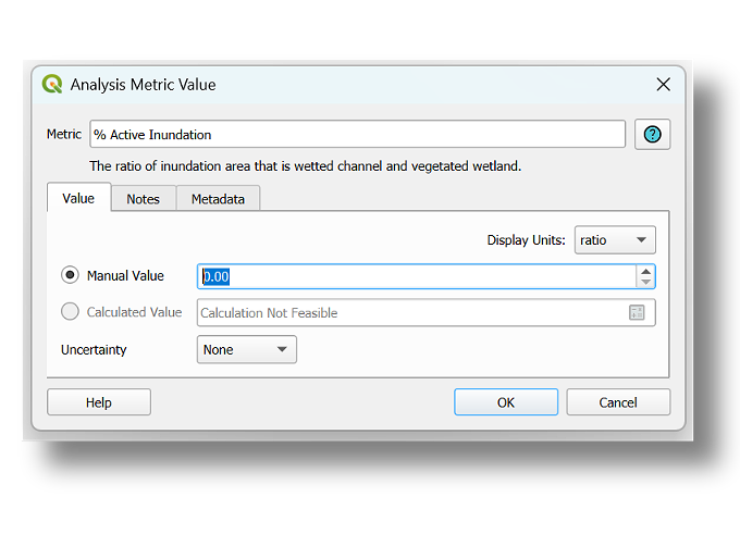
Users have flexibility to change metric values, units, and uncertainty under the metric properties denoted by the blue pen symbol (10). In the properties window, users have the option to change metric values from their automated calculation to a manual entry, add uncertainty values (entered manually), or change the display units under the Value tab. Users can (optionally) add more information about the metric under the Notes and Metadata tabs. To view metric information as defined in the protocol xml, click on the blue question mark in the upper right hand corner.
Export an Analysis
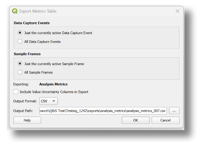
Finally, users can export their analysis table by clicking on the Export Metric Table (11) in the bottom right hand corner. This can be done for one or all DCEs and sample frames. The default location will be the Exports folder in the QRiS project, but the user can specify any file location if desired.
Open An Existing Analysis
To view an existing analysis in the QRiS project tree, right click on an existing analysis under the Analysis bin and select Open. This will open the analysis dockable window. You can reposition this window by dragging the title bar to suite your needs.
Analysis Summary
Currently being reworked.
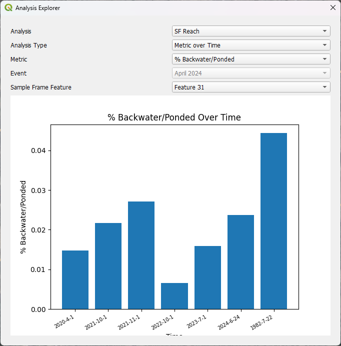
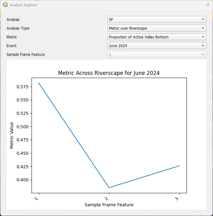
Clicking the blue logo next to properties will open a new window where you can see your calculated metrics displayed as a graph. This is also accessible by right clicking on the analysis folder in the main QRIS project tree.
- The Analyis dropdown lets you choose which analysis you want to look at if multiple exist.
- The Analysis Type allows you to choose to visualize your metric two ways
- Metric over Time - this will show metric values for chosen sample frame over the timespan from each DCE.
- Metric over Riverscape - this will show your metric values from one individual DCE changing from one sample frame to another, or longitudinally through your riverscape.
- The Metric dropdown allows you to choose the metric you would like to visualize.
- The Event dropdown allows you to switch between DCEs, this is only applicable when Metric over Riverscape is chosen.
- The Sample Frame Feature dropdown allows you to switch betwewn sample frames, this is only applicable when Metric over Time is chosen.
Delete an Analysis
Right click on an analysis in the QRiS project tree and select Delete. This will delete the analysis and all of its metric values. You cannot undo this action.